In Stock! Maytech V1.0 Analog Voltage to PWM Converter ADC to PWM Signal Converter 0-5V Analog Input to 0-100% PWM adjustable 0.8-2.2ms 100HZ PWM Output
In Stock! Maytech V1.0 Analog Voltage to PWM Converter ADC to PWM Signal Converter 0-5V Analog Input to 0-100% PWM adjustable 0.8-2.2ms 100HZ PWM Output
SKU:MTAPC-V1
Couldn't load pickup availability
Have Doubts? Contact US!!
Have Doubts? Contact US!!
Maytech V1.0 Analog Voltage to PWM Converter ADC to PWM Signal Converter 0-5V Analog Input to 0-100% PWM adjustable 0.8-2.2ms 100HZ PWM Output
Options:
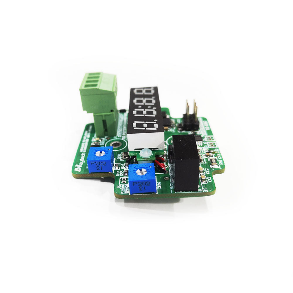
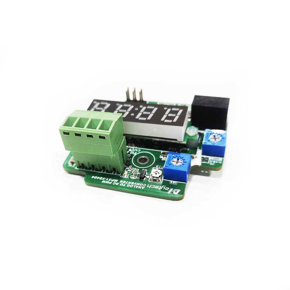
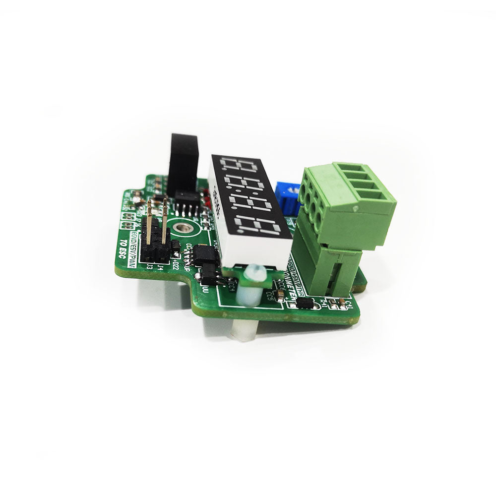
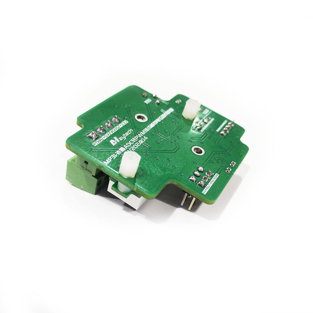
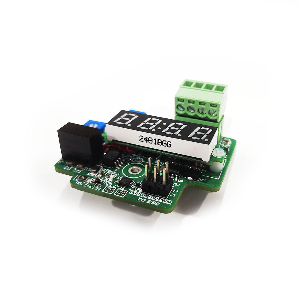
Version1: PCB only without case
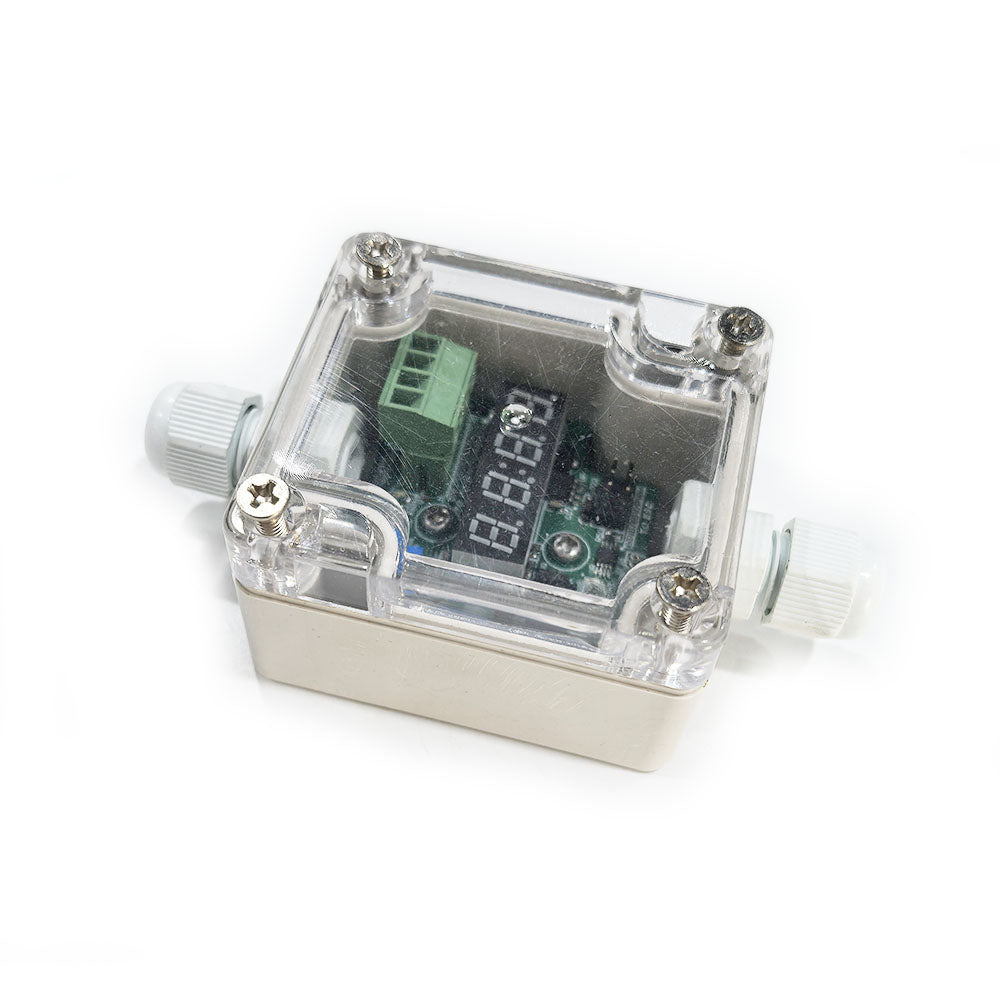
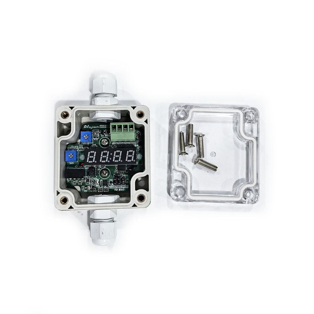
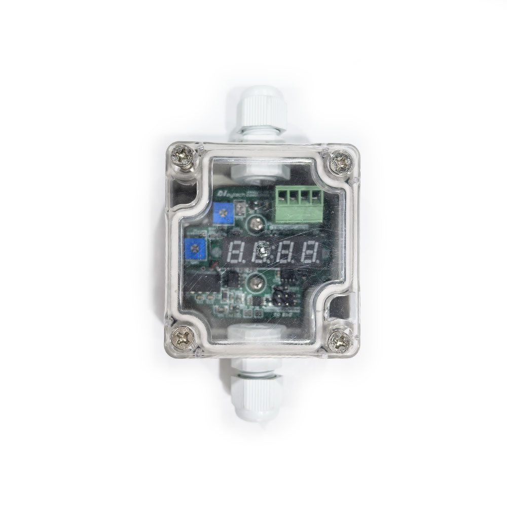
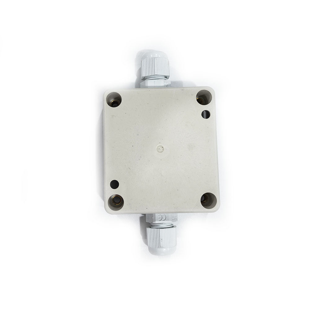
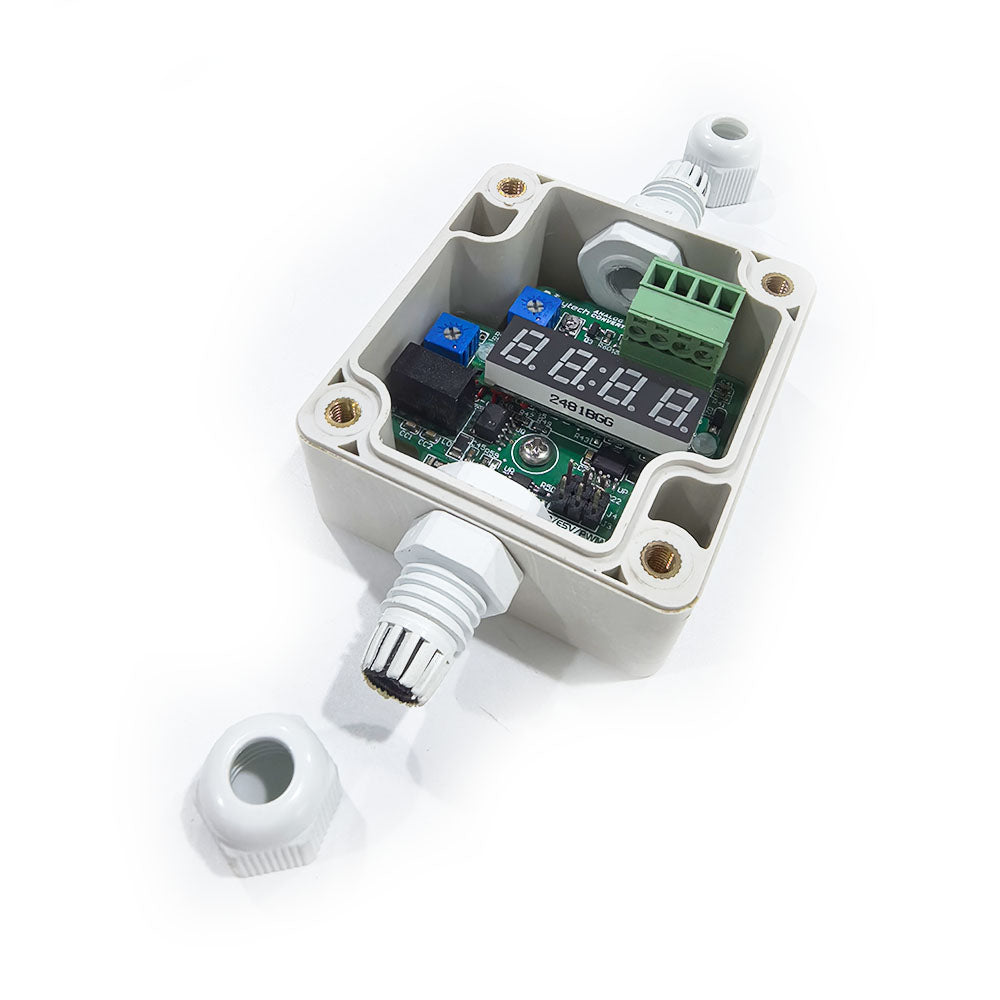
Version2: PCB with plastic case (non-waterproof), you can modify case and fill it with some glue to make it waterproof)
Notice before order:
- The silk-screen printing of content, font, font size, etc. of each batch may change. The actual arrival of the product shall prevail.
- Please read manual before order and make sure you know if it's suitable for your applications and how to use it.
Specifications:
PWM signal output frequency 100Hz, voltage peak 4.5V.
Voltage: Converter board needs 5V power from ESC or UBEC and supplies 5V/3.3V to the ADC device (not grounded with the ESC or UBEC 5V).
Current: The converter board requires a maximum of 200mA from the ESC or UBEC, and provides a maximum of 50mA to the ADC device.
ADC input signal range: 0-5V, and the difference between the maximum and minimum values must be greater than 1V.
PWM output signal range: 0.8-2.2ms, and the difference between the maximum and minimum values must not be less than 0.2ms.
Conversion error: less than 0.5%.
Application: Use ADC (analog) signals from potentiometers, pedals, ebike twist throttle, thumb throttle, marine electronic throttles, industrial PLCs, etc. to control the speed of the Maytech brushless power system.
Advantages:
1. Adopt industrial-grade isolation solution, use isolated power supply and optical coupling technology to enhance anti-interference ability, and the ADC input length can reach more than 5 meters.
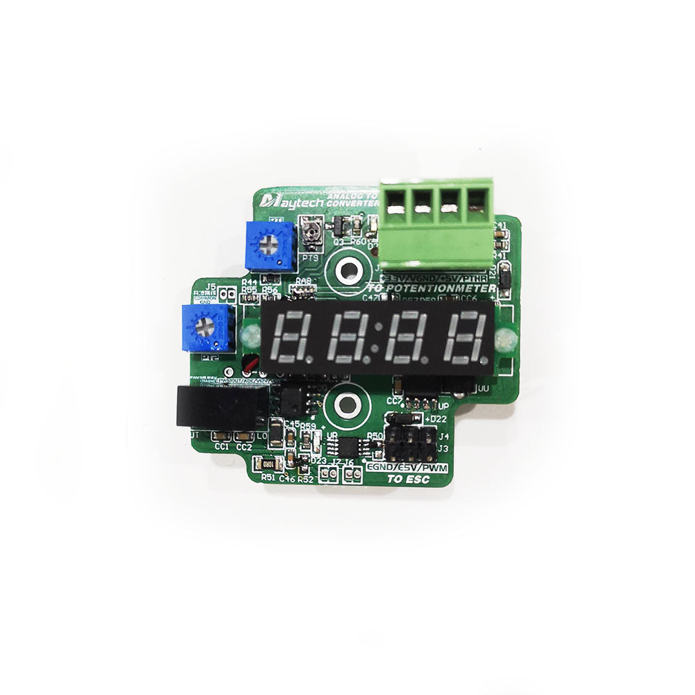
2. ADC voltage signals of different ranges can be proportionally adjusted through potentiometers to output the PWM signal you want, and there is a pulse width digital display during the adjustment process, which solves the disadvantages of traditional converters with fixed ranges or the need to use an oscilloscope to adjust the output range.
3. The ADC signal port has a protection function against spike pulses.
4. The PWM output driver uses a high-speed operational amplifier with a driving capacity of 80mA per channel.
5. It can output two PWM signals with the same pulse width at the same time to control the simultaneous operation of two ESCs.
6. Optional waterproof case for all weather conditions. (Optional waterproof case needs to be bought separately).
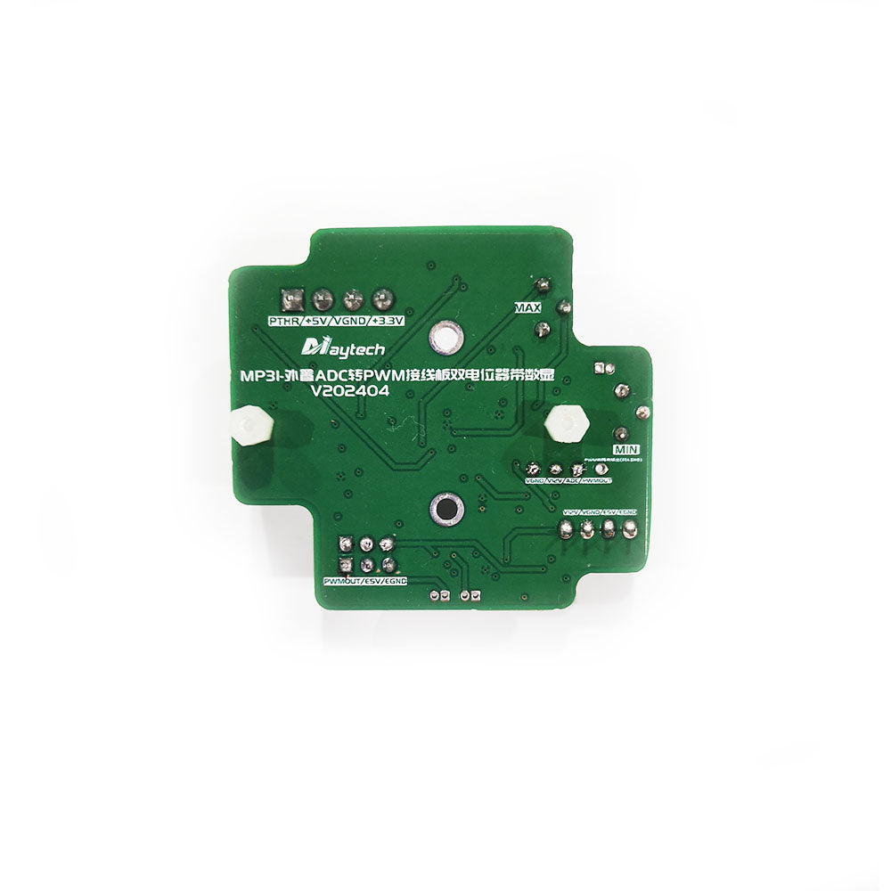
Wiring Diagram:


Mapping Adjustment - How to Convert Analog Signals to PWM Signals?
Different devices have different ADC voltage signal definition ranges. For example, the e bike throttle is 0.8-4.4V; the rotary potentiometer is 0-5V; and the output of some microcontrollers is 0-3.3V. Therefore, it is necessary to map the voltage range of the input signal to the correct pulse width range of the output signal. Usually, the PWM signal pulse width range of the Maytech ESC is 1.1-1.9ms (for ESCs without throttle calibration setting) and 1.0-2.0ms (for ESCs with throttle calibration setting). The following uses the mapping of e bike twist throttle voltage signal to PWM 1.1-1.9m as an example to introduce the adjustment process.
1. Connect all devices and ensure that the ESC is not connected to the motor to prevent accidents.
2. Turn PT1 (PWM pulse width adjustment potentiometer) clockwise ↻ to the maximum and PT2 (PWM pulse width starting point adjustment potentiometer) Counterclockwise ↺ to the minimum.
3. Power on the ESC, and the signal cable of the ESC outputs 5V to power the conversion board. The power indicator of the conversion board is on, and the pulse width display meter has numbers.
4. Counterclockwisely ↺ reduce PT1 (PWM pulse width adjustment potentiometer) step by step, and constantly observe the pulse width meter value at the maximum and minimum throttle of the handlebar. When the maximum pulse width minus the minimum pulse width is equal to 0.8ms (1.9-1.1=0.8ms) (if your ESC needs 1-2ms PWM, then you need to adjust this to 2-1=1ms), PT1 adjustment is completed.
5. Turn the handlebar throttle back to zero, and turn PT2 (PWM pulse width starting point adjustment potentiometer) clockwise ↻. When the handlebar throttle is at zero, the pulse width meter shows 1.1ms, and PT2 adjustment is completed. .
6. Repeatedly increase the throttle from zero to maximum and observe whether the output pulse width is between 1.1-1.9ms. The mapping adjustment is now complete.
Special tips:
1. The factory default values maybe not what the user needs. After the product arrives, please be sure to adjust the input and output range mapping according to the above introduction Term “Mapping Adjustment”
2. This product requires experienced users to wire and configure. During use, be sure to ensure the safe operation of each device in the brushless power system (including but not limited to batteries, motor controllers ESC, main controllers ECU, programmable controllers PLC, brushless motors BLDC, switching power supplies SMPS, DC-DC/UBEC, etc.).
3. Our company does not promise that this product is suitable for the user's brushless power system and does not bear any risks of this product and other products!
Other Instructions
1. Pay attention to the throttle ADC value when powering on. Do not give the maximum throttle when powering on. Especially for Maytech ESCs with throttle calibration setting, giving the maximum throttle when powering on will enter the throttle calibration process or throttle parameter programming mode, resulting in startup failure! ! !
2. This converter only supports forward mapping conversion, that is, the ADC voltage increases, and the output PWM pulse width also increases. Reverse conversion is not supported. If this function is required, please contact Maytech for customization.
3. The input signal of this converter is only the ADC voltage signal. For the 4-20mA signal commonly used in the industrial field, please connect a 200 ohm resistor in parallel to convert the current to 0.8-4V voltage. For 0-10V signals, please use resistors to form a voltage divider network to convert the voltage to within 5V and input it to the converter.
4. This converter is powerful, uses more components, and is larger in size than the common simple function converters on the market. Please reserve enough space during installation.
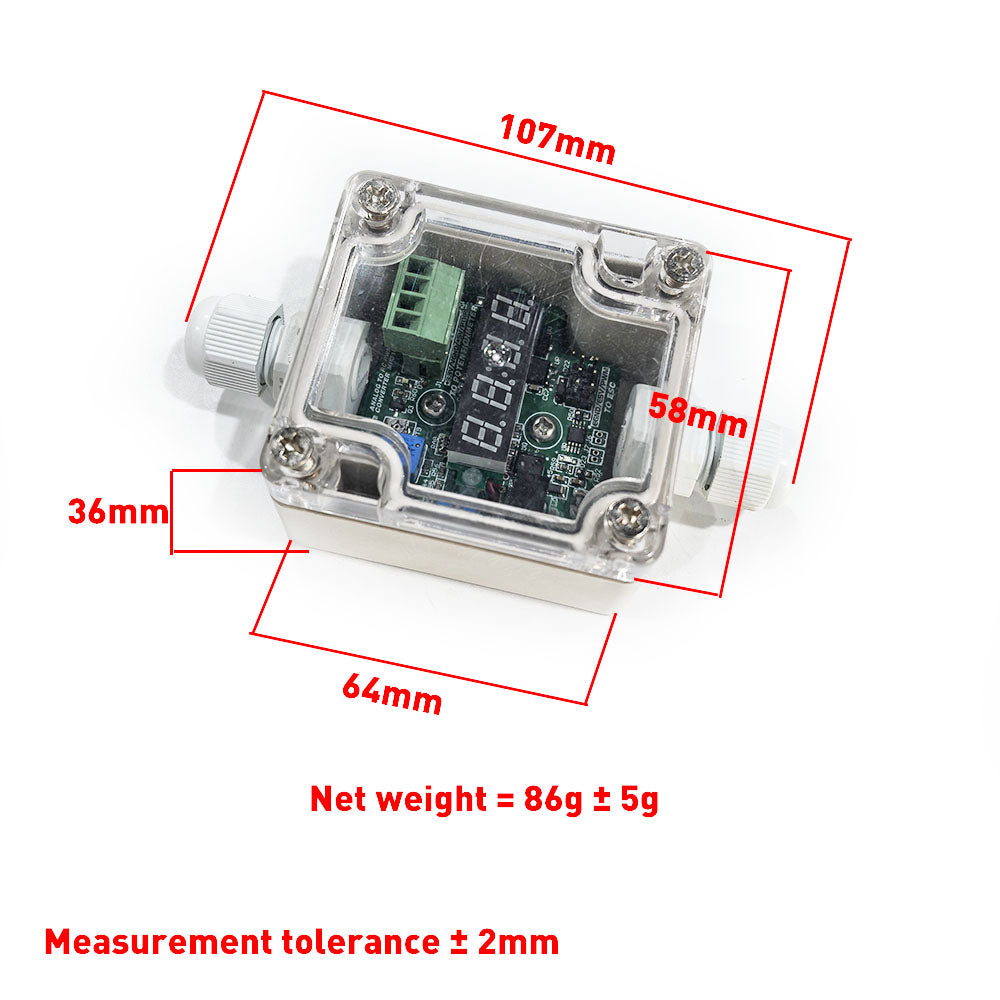
Attached with dimension drawing: