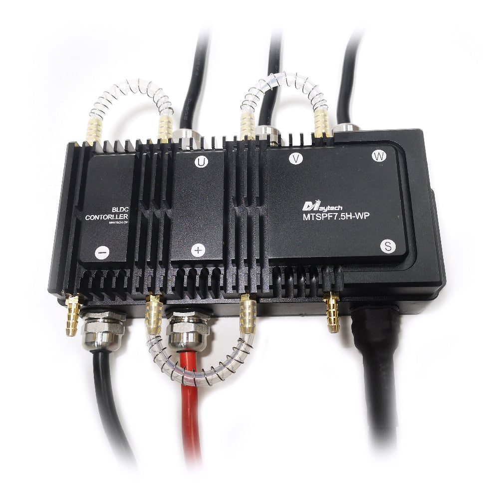
Maytech IP68 Fully Waterproof 300A VESC75 based speed controller For Electric Boat Surfboard Efoil
Maytech IP68 Fully Waterproof 300A VESC75 based speed controller For Electric Boat Surfboard Efoil
SKU:MTSPF7.5H-WP
Verfügbarkeit für Abholungen konnte nicht geladen werden
Have Doubts? Contact US!!
Have Doubts? Contact US!!
Recommend 300A 80V Anti-spark Switch:
Maytech IP68 Fully Waterproof 300A VESC75 based speed controller For Electric Boat Surfboard Efoil
1. Introduction:
MTSVESC7.5H is based on 75V 300A VESC hardware and firmware construction. It is mainly used for controlling brushless motor on mobile devices with 18S and below Lipo battery(max 75V). Compared with original 75V 300A VESC, it has better heat dissipation and greater continuous power!
2. Application Field:
With the many functions and interfaces of VESC, MTSPF7.5H-WP can be widely used in high-speed electric scooters, high-speed electric karts, electric motorcycles, electric boats, electric surfboards, heavy-duty cargo robots, fighting robots, Electric forklift, and various special vehicles, etc.
3.Specifications:
|
Model no
|
MTSPF7.5H-WP
|
Motor Current Max in VESC_TOOL
|
≤300A
|
|
Voltage
|
25V-75V
|
Absolute Maximum Current in VESC_TOOL
|
≤350A
|
| Support | Sensored and Sensorless Motors | Battery Current Max in VESC_TOOL | ≤150A |
|
Lipo
|
5-18S
|
Hardware version
|
based on VESC 75/300
|
|
Firmware
|
Upgradable, Compatible to VRSC_TOOL
|
Capacitors
|
24pcs
|
|
BEC
|
Yes
|
Size
|
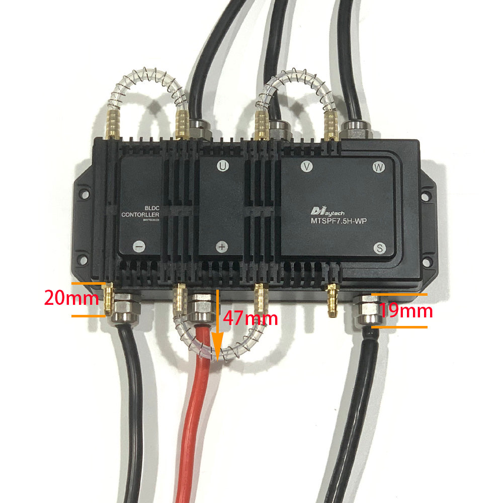
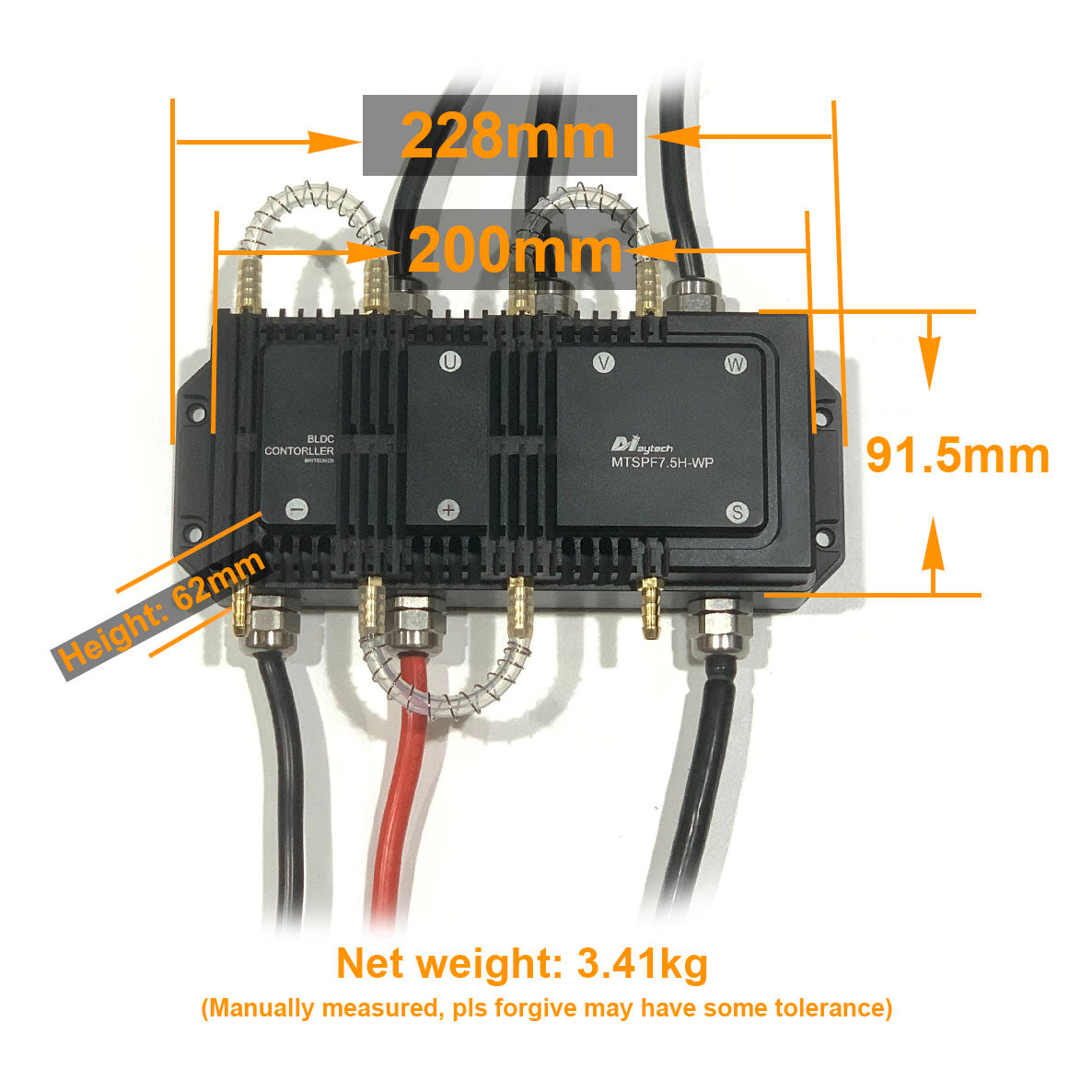
About 228*91.5*62mm
|
|
Application
|
electric skateboard, fighting robot, e-bike, electric motorcycle, efoil, electric surfboard, watercraft, electric boat, underwater ROV, etc
|
||
Motor Current Max: ≤300A (According to your motor current)
Absolute Maximum Current: ≤350A (According to your motor current)
Battery Current Max: ≤150A (According to your battery discharge current)
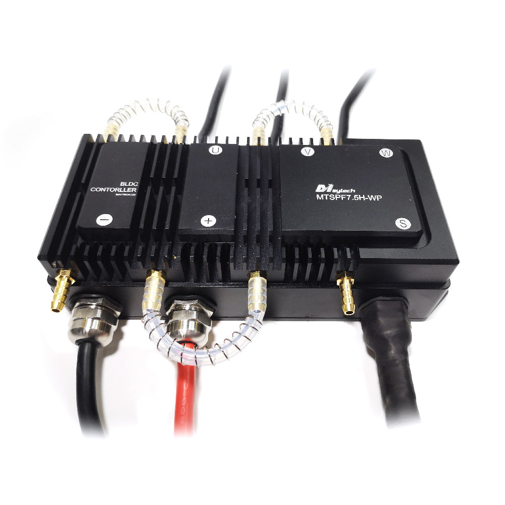
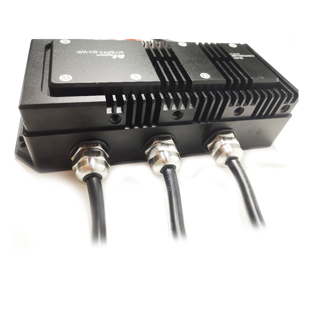
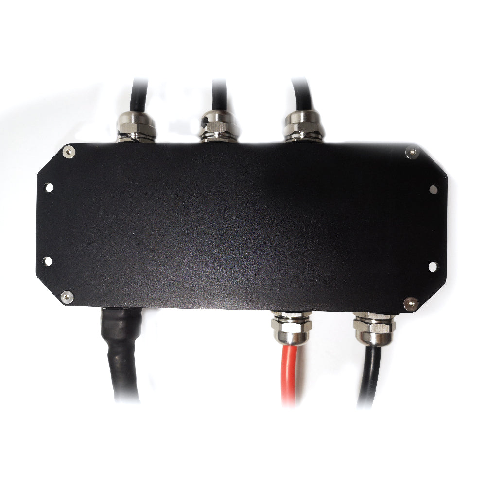
With IP68 waterproof aluminum alloy case and waterpoof glue inside of the case.
Compatible with VESC_TOOL, programmable;
Use High voltage components, more stable, better performance;
With 24pcs mosfets;
With high quality machined aluminum case;
With Great heat dissipation for high voltage and high current applications;
High voltage: max 75V
High current: 300A
Compatible with brushed and brushless motors, intrunner and outrunner motors
Sensored or Sensorless operation + Hybrid mode
Adjustable Forward/Backward/Brake
Regenerative Braking Function
Configurable RPM, Current, Voltage and Power limits
Support PPM, Analog (ADC), UART, Canbus input
Support BLDC square wave mode control and FOC sine wave mode
Communication ports: USB, CAN, UART
Throttle curve and ramping for all input sources
Seamless 4-quadrant operation
Motor Revolution, Amp Hour, Watt Hour counting
Real time data analysis and read out via communication ports
Adjustable protection against:
- Max and Minimum Input(Battery) Voltage
- Max Motor Current and Input(Battery) Current limits
- Max ERPM(RPM) (separate limits for each direction)
- Max Power (Wattage)
- Max Motor and ESC Temperature
- Max Regenerative Braking Current (separate limits for the motor and the input)
Notice:
-
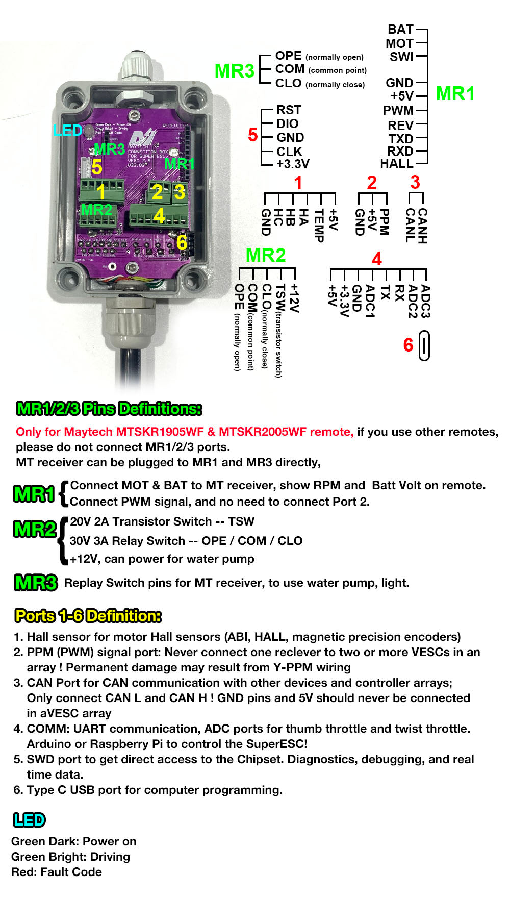
Never connect one reclever to two or more V6/V75 based SUPERFOC ESCs or VESCs in an array! Permanent damage may result from Y-PPM wiring.
-
Only connect CAN L and CAN H ! GND pins and 5V should never be connected in a V6/V75 based SUPERFOC ESCs or VESC array.


- CNC aluminum alloy heat dissipation case, optional water cooling system and Waterproof cooling system.
- Separate design of strong and weak current circuit boards. The strong current MOS board is 6x3oz immersed gold, with attached 3mm² and 6mm² cross-sections copper bars for high-current routing.
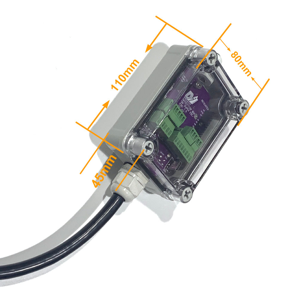
- The weak current circuit adopts the USB-Type C interface, and through EMC optimization, the USB can communicate well with the PC even when ESC strong current circuit works at high voltage and high current.
- Proprietary 5V and 12V external power supply interfaces will not cause interference when powering analog circuits such as twist/thumb throttles.
- The strong current circuit uses 24pcs FDBL0200N100 N-MOS. The theoretical instantaneous withstand current is close to 1200A! Beyond the original VESC 75V 300A!
- Use TI UCC27211 independent Driver. The driver current is 2.5 times higher than DRV8301/8302, and the driver speed is 3 times faster. It can realize the nanosecond turn-on of the MOS tube, and improve the motor operation effect under high ERPM. The maximum ERPM can reach 140 000.
- 9pcs 80V 470uf high frequency low resistance capacitors. The capacity far exceeds other commercial VESCs on the market.
- The high-current cold-pressed terminal connection structure makes the connection more stable and less heat-generating.
- Built-in 3.3V/5V switchable power supply for Hall/Encoder. The power supply voltage can be adjusted to adapt to your Hall/Encoder board.
- MOSFET: American Fairchild FDBL0200N100 ( Fairchild, which has been acquired by ON Semiconductor).
- Driver IC: American TI company UCC27211, which is also used on original 300A 75V VESC .
- Current High-Speed Sampling Chip: American TI Company INA240. It can make the current sampling faster and more accurate, and has a good improvement on the FOC and over-current protection functions.
-
DC-DC module:
The first stage DC-DC uses TI's LM5161 to convert the main power supply voltage to 12V;
The second stage of DC-DC uses classic LM2940 to convert 12V to 5V, max supply current is 1A.
The third stage of DC-DC uses low ripple STC2321, convert 12V to 3.3V, max supply current is 2A.
Above power supply configuration make smoother voltage output, reducing the abnormality of MCU and other devices caused by unstable power supply.
-
CANBUS interface chip: TJA1051 from NXP company.
-
Encoder: This ESC does not integrate the AS5047 encoder chip. If necessary, please purchase the encoder board separately.
8. Notice before usage.
8.1 Although the 7.5H function is powerful enough, there is still heat in the case of high current application, so we must do a good job of heat dissipation! If place it in a sealed container, it must be forced to be cooled with water.
8.2 Before the new ESC is officially used, please test it with a low-voltage and low-throttle, after success, then slowly increase voltage and throttle. Be sure to pay attention to safety during this period!
8.3 Recommend to add an electronic switch with short circuit protection function between the ESC and battery, such as MTS2009AS 300A electronic switch or BMS with switch function. It is not recommended to use only contactors without short circuit protection!
8.4 The battery and motor side terminals must be connected tightly, they can’t be loose. Also please make sure terminals not touch case or other wires.
8.5 In actual use, please use hot melt glue to fix the hall/UART interface cables the corresponding sockets of the ESC, to prevent the cables to loosen due to the bumps of the vehicle!
8.6 Please do not disconnect relay switch or electronic switch with load! Otherwise
it will cause electromagnetic interference, which might damage the VESC.
8.7. Summarize the occasions where the duty cycle mode can be used: fighting robots, differential cars, robot joint positioning, 3D printers, and model drones. Don’t use it in e-bike/etc, it’s easy to throw people away and burnt the ESC.
Currend mode is suitable for e-bike application.
Check each control mode difference: https://michobby.com/blogs/news/whats-the-difference-of-vesc-current-mode-duty-cycle-mode-and-pid-speed-control-mode
8.8 If you use the VESC to work with our MTSKR1905WF remote on Esurf/ Efoil, please noted below settings:
Our remote PWM signal output pulselength in Esurf mode is 1-2ms, no brake no reverse, and in VESC default pulselength is 1ms start, 2ms end, 1.5ms center, so if you will use our remote in Esurf mode, then please adjust below settings in VESC_TOOL:
PPM Control Type: Current no reverse
PPM Mapping: Pulselength Start: 1ms; Pulselength End: 2ms; Pulselength: 1ms
The above tips are only suggestions based on the experience of our engineers. how
to actually operate is up to you. Parameters for different setup is also different,
please noted.


Share
